Search

Showing posts with label Mobile techniques. Show all posts

Sunday, 20 November 2016

HOW TO RESTORE THE BACK UP RPLWHEN A PHONE HAVE DAMAGE IMEI OR SIM LOCK AREA

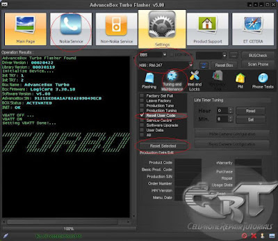
I have already back the phone RPL but now the phone have damage IMEI or Simlock area how to restoreit?

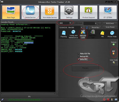
1. Choose Nokia Service Tab
2. select BB5 option 
3. click IMEI and Lock option
4. Check the Write RPL option
5. Press Process


HOW TO UNLOCK BB5 PHONES USING ADVANCE TURBO FLASHER ATF BOX

How to Unlock BB5 Phones Using Advance Turbo Flasher ATF Box
1. Choose NOkia Service
2. Select BB5 button option
3. Select IMEI and Locks tab
4. Mark Simlock option
5. Choose any methods of unlocking
or just by then select Unlock by SimlockRPL


A- NCK CALC PM308
u can use for unlock this models

RAPIDO: (SL1)
============
* N95 (RM-159)
* N95 (RM-245)
* N95 (RM-160)
* E90 (RA-6)
=======================
RAP3GV2 models: (SL1)
==================
* 6630 (RM-1)
* 6680 (RM-36)
* 6681 (RM-57)
* 6682 (RM-58)
* N70 (RM-84)
* N70-5 (RM-99)
* N71 (RM-67)
* N90 (RM-42)
* N91-1 (RM-43)
* N91-8GB (RM-43)
* N91-5 (RM-158)
* N93 (RM-55)
=======================
Rap3Gv3 phones: (SL1)
====================
* 3109c (RM-274) -
* 3110c (RM-237) -
* 3250 (RM-38)
* 3500c (RM-272)
* 3500cb (RM-273)
* 5200 (RM-174)
* 5200b (RM-181)
* 5300 (RM-146)
* 5300b (RM-147)
* 5500 (RM-86)
* 5700 (RM-230)
* 5700 (RM-302)
* 6085 (RM-198)
* 6086 (RM-188)
* 6086b (RM-260)
* 6125 (RM-178)
* 6126/6133 (RM-126)
* 6131 (RM-115)
* 6131 NFC (RM-216)
* 6136 (RM-199)
* 6151 (RM-200)
* 6233 (RM-145)
* 6234 (RM-123)
* 6280/6288 (RM-78)
* 6290 (RM-176)
* 6300 (RM-217)
* 6300b (RM-222)
* 7370 (RM-70)
* 7373 (RM-209)
* 7390 (RM-140)
* 8600 (RM-164)
* E50 (RM-170)
* E50 (RM-171)
* E50 (RM-172)
* E61 (RM-89)
* E61i (RM-227)
* E62 (RM-88)
* E65 (RM-208)
* N73-1 (RM-133)
* N73-5 (RM-132)
* N75 (RM-128)
* N76 (RM-135)
* N76 (RM-149)
* N77 (RM-194)
* N80-1 (RM-92)
* N80-3 (RM-91)
* N92 (RM-100)
=================

B- NCK CALC PM120
u can use for unlock this models

Rapido SL2
============
* 5800
* 6110
* 6120c
* 6121c
* 6124c
* 6210
* 6220c
* 6290
* 6650
* E51
* E66
* E71
* N78
* N79
* N81
* N81 8gb
* N79
* N82
* N85
* N95 8gb
* N96

bb5+ (SL2)
============
* 3120C
* 3555
* 3555b
* 5310 - (V58.58; V59.59 NOT SUPPORTED)
* 5310b
* 5610
* 5610d
* 6263
* 6300i -(V57.20 NOT SUPPORTED)
* 6301
* 6500S - (V59.60 NOT SUPPORTED)
* 6500C - (V59.45 NOT SUPPORTED)
* 6555
* 7500
* 7900
* 8800
============

C- UNLOCK BY SIMLOCK RPL
u can use for unlock this models

THIS THE BEST WAYT TO UNLOCK ALL TYBE OF BB5 PHONES (SL3 NOT SUPPORTED)

HOW TO USE TURBO MODE FOR POWERFUL SPEED IN FLASHING USING ADVANCE TURBO FLASHER

This is the coolest part using Advance Turbo Flasher for its Powerful Flashing Speed capability that lets flashing time consumption less than other flashing devices.

 To Activate fast speed turbo flashing just select and click
                                                                                      Turbo Mode option in the software window.


HOW TO RESET USER CODE WITHOUT CLEARING THE USERS DATA USING ADVANCE TURBO FLASHER

Resetting user code without clearing user data on the mobile phone handset.

1. Select Nokia Service Tool
2. Choose Tuning and Maintenance option
3. Check Reset User Code option
4. Press Reset Selected


HOW TO UPDATE ADVANCE TURBO FLASHER ATF BOX TO LATEST VERSION

How to Update Advance Turbo Flasher ATF Box to Latest Version?
Just open the the advance turbo flasher software and Product Support  tab then hit Restore Box.
An updating text will then show up, follow the steps of the process and wait till done.


ADVANCE TURBO FLASHER (ATF) BOX FLASHING VIDEO TUTORIALS


Here's a few methods and step by step procedure on how to use Advance Turbo Flasher (ATF) Box   for Flashing some various mobile phones handsets.

Advance Turbo Flasher C5 Fbus Full Flashing


Flashing on Nokia N900


Flashing on X6 


Flashing on 1202


ADVANCE TURBO FLASHER TO MT BOX 10 PIN CONVERTER SCHEMATIC

This is a schematic of a converter for using mt box 10 pin cable with advance turbo flasher box 
                   

               10 pin cable with advance turbo flasher box

WHAT IS ATF [ADVANCE TURBO FLASHER] ?

ATF [Advance Turbo Flasher] Features: Unique Hardware Features: 480 mbps HIGH-SPEED USB 2.0 Connection ( First In World ) - PC connection is 40 times faster than any other box in the market 100% FPGA based implementation of the flash bus protocols( First In World ) -Significantly faster and more stable than regular MCU based boxes Adjustable VCCIO Logic Levels (3.30v, 2.80v and 1.80v) -Compatible with old phone model Logic Level (3.30v) -Compatible with new phone model Logic Level (2.80v) -Compatible with future phone model Logic Level (1.80v) Proper ESD protection on the FLASHBUS port -Protects phone damage due to Electro Static Discharge Ultra Fast Flash Clock currently upto 15 Mhz (First In World ) -Firmware updatable to support upto 60 Mhz without the need of hardware modifications Internal VPP Flash Voltage Generator (3.0v, 5.0v, 9.0v and 12.0v) -Makes Flash Erasing on slow phones faster -Does not require external power adapters to generate 9.0v and 12.0v -

BASIC MOBILE PHONES HARDWARE REPAIR TROUBLESHOOTING TECHNIQUES TUTORIAL

Fixing hardware problems is not been easy and takes a lot of time to consume rather than software problems, it is because when it comes to software handling you don't really need to open or dismantle a mobile phone handset, because only few of them really need to. In most cases like this, many among mobile phones technician focus on software handling like especially unlocking, for it less time consuming and more flexible to do with. This is been true that mobile phone technicians were separated into two specialties, like Hardware expert and Software expert, that is what the term they called it; It because mobile phones is a combination of software and hardware mechanism.
But there are also many mobile phones masters that can manage and do both hardware and software specialty and skills. They gained this knowledge by years of experience, and not only that they also earned much more income rather than to those staying at one particular specialty. 

Now, here is the basic step by step repair procedure on hardware troubleshooting on mobile phones. Various mobile phones have different circuits and components or parts layouts and designs. First thing you must learn and be familiar with is, how each circuit components or parts is being mounted, connected, assembled or designed.


First step in handling troubleshooting procedure.
1. Visualization Checkup- Before proceeding to anything always consider the fact that a mobile phones handset is fragile object. Check and have take a look around every inch of the handsets package and layout, In this manner you can identify if the handset is in repairable condition, something like checking the whole printed circuit board components and parts, if it is free from dust,corrosion, bended,breakageetc.
2. Know the Phones Status - Ask the the user or the costumer about the phones history before the problem occurs. Letting know the phones history like accidentally soaked into a liquids or water, dropped,throwned and etc.
In this manner you can get an idea where to start or begin with. 
3. Do Software Check up - Use a certain flashing device for that particular handset product to be able to read logs, logs is a reading of mobile phones firmware programmed and installed unto it. This is a big help for most advance mobile technician this days, A logs reading can help you where the faulty line or parts occurs. If you are not familiar about how to read logs you can ask to that certain flashing device product supporters and creator.
You can do flash, reformat at first hand if found something wrong with the mobile phones firmware. If all methods of software already done and nothing happens, proceed to hardware troubleshooting.

4. Analyze The Circuit - After dismantling and do visualization check up,be patient and take your time to analyze the whole circuits layout, and think of a step by step plan procedure in your mind where or how to begin with. A Special Operation Procedure is good way and a reliable source of idea within yourself, not only by enhancing your skills but you are also practicing a self discipline method.

Now lets take one example of basic hardware troubleshooting methods in one particular mobile phone handsets. In this simple way you can then manage how to troubleshoot or been able on finding faulty parts or components within a mobile phone circuitry.

An example here is Nokia 6300, now assuming that this handset having a faulty microphone or mouthpiece. 


Do the basic procedures mentioned above, assuming that you are familiar with the  Mouthpiece or microphone circuit, and already  know how to check a microphone or mouthpiece component.
you can now do this step below;

1. Find any available schematic diagram and locate the microphone circuit layout on it. Remember where each parts and components location and do a mapping like this.

                               
2. Use a multi-tester and check the pads for a short circuit, this is not always happen but it is also unpredictable to a mobile phones short circuit might occurs, you are not checking the outer mounted components but the internal lines with it. Just set the tester to x1 resistance value, I preferred analog multitester in this lesson for it is cheaper to purchase rather than the digital. Now connect both test probe to the inner and outer layer of the mouthpiece terminal pads, then do it again in opposite manner, a short circuit have both readings closer to zero ohms. 
                           nokia 6300 mic tracing
3. Trace the line paths between the first or the closest component connected to each terminal pads.
The circuit diagram shows that there are coil filter in both lines, connect the tester across each coil terminal leds, your not just checking the lines here but also checking the the coil as well.
                           
4. Now the next step is to leave behind the line paths between the coil to the EMI-Filter for it is uncheckable beyond that paths for the EMI- filter is an IC. you need to remove it first before you can check on that lines , which will be done later at the last steps of procedures. Now next to move on to the opening lines and component where the test probe can connect with, the two filter capacitors and both coils which are an open path where you can connect the test probe on it. now connect or attach both probes at the end of each line indicated in red. 
                           
5. Now check the remaining open path which is the Resistor, you can't check the line paths on those area for it ends up connected to Retu IC. So just then proceed to check its resistance value instead. 
                             
6. If all those mentioned lines above is all in good condition you may now proceed to suspect the EMI-Fiter is having a problem or faulty. You then now remove it from the Printed circuit board then do a line check up from the mouthpiece terminal to that EMI-filter terminal bumps where it is being connected. 
                     
You can refer to the schematic diagram for each terminal specification. You may now can check the IC itself by analyzing the internal circuitry inside it. I advice just replace a good and working one if not so sure about. 
                  
8. It this step is most complicated job to do with, specially for beginners.This is one of advance troubleshooters skills.  If found all of those line paths and components above were in good conditions. The last part is to work a power management IC itself for the audio codec circuit is also within that chips.
Now, if the last and final suspected parts is the chips, you must need to rework it, Reheating it the first will do and might as well also work. But if the problem still remain, Reworking it is the best advice that suites out.
but also do not forget to check the line paths between the mouthpiece circuit area, while the chips is being remove and out on the PCB layout, it is a proper time to check the ball bumps terminal where that certain microphone is being connected. an example of tracing the ball bumps terminals below.
                  
okay, that's it for a while, for there are lots of techniques we are going to tackle sooner, hope you do understand a little bit with this method.

Page Numbers

Contributors